Step 0
Damit wir die Drucker schneller verschicken können, wurde die Slider für XYZ noch nicht angepasst. Dafür liegt aber PTFE Spray bei. Die Anpassung dauert circa 5-10Minuten pro Slider. Dazu das Aluprofil ein den Slider schieben, einmal auf der Rückseite des Sliders leicht ein zwei Mal draufklopfen. Das Aluprofil wieder rausziehen und den Vorgang wiederholen. :) Damit beim Z Slider (der mit der Motorhalterung) nichts abbricht bitte nicht an den Halterungen ziehen sondern direkt an der Einführung für das Aluprofil. Wenn es sich die Slider gut hin und her schieben lässt, etwas PTFE Spray auf das Aluprofil und in den Slider sprühen. Dann draufschieben und nochmal 1-2Minuten schnell hin und her ziehen. Fertig.Step 1
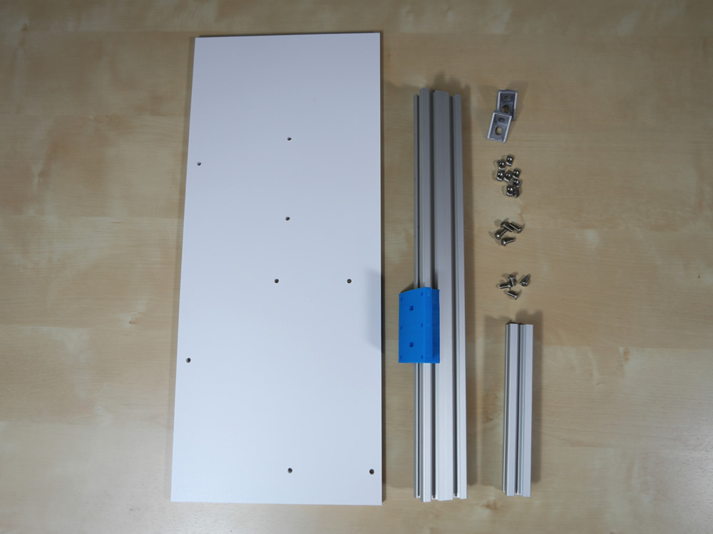
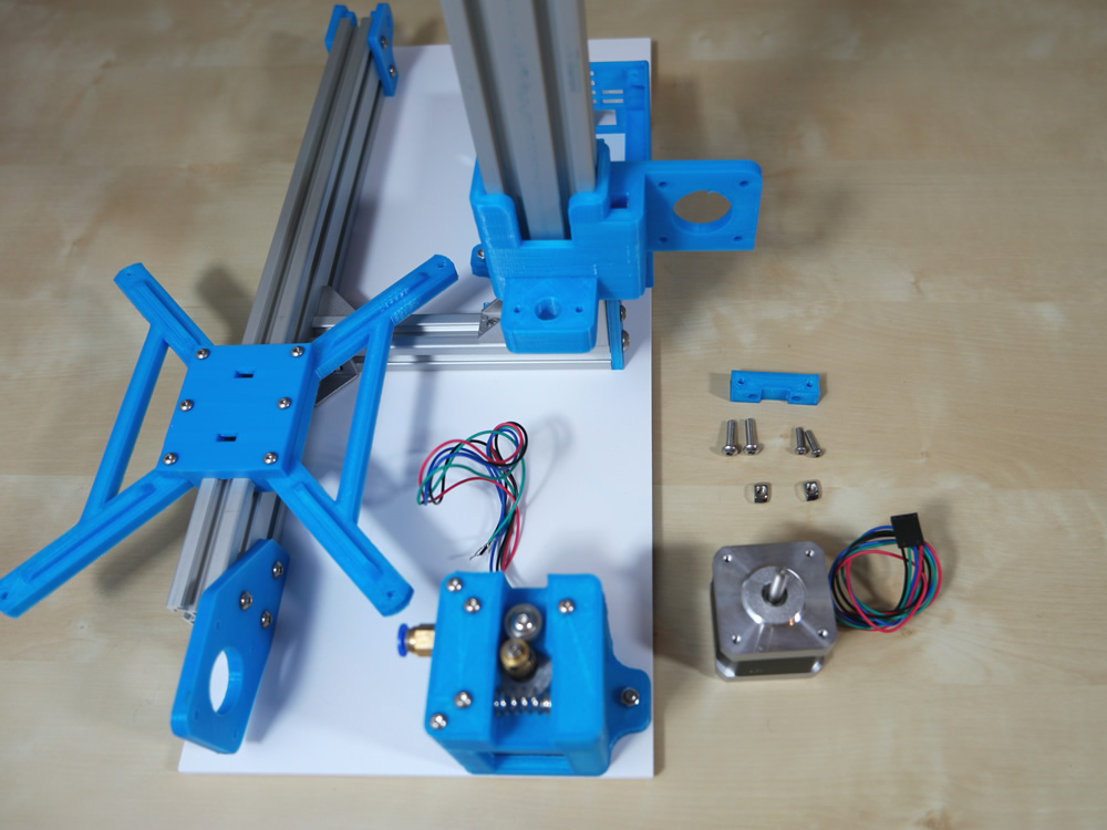
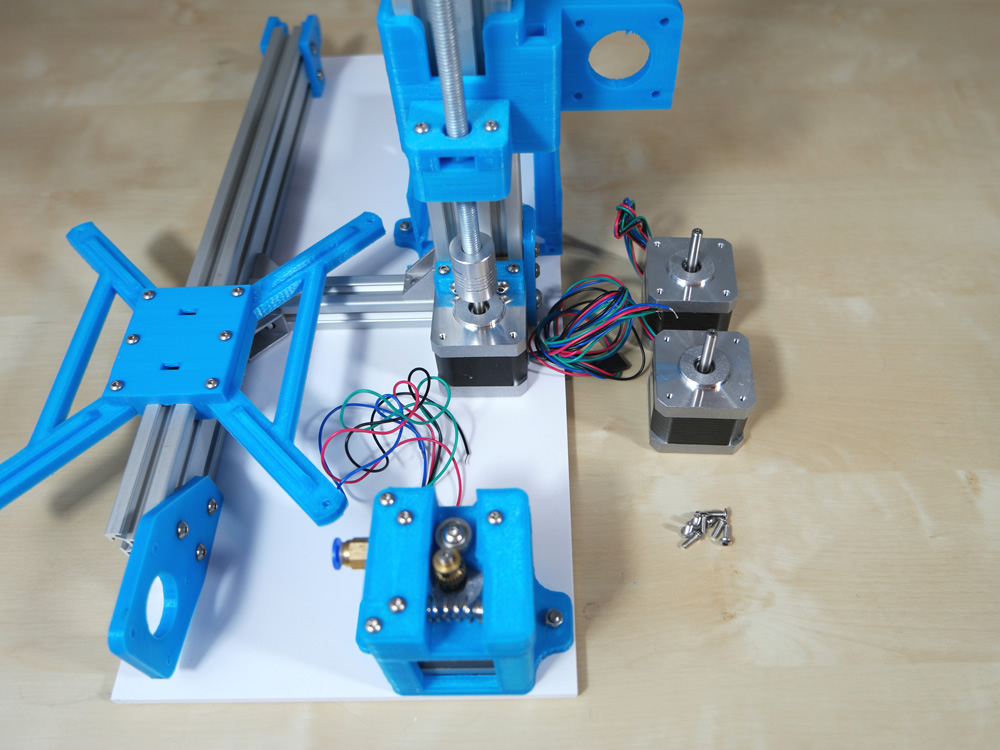
- 1x Plate
- 1x Alu Profile 35cm
- 1x Alu Profile 14cm
- 2x Fitting Angle
- 8x M4 Hammer Nut
- 4x M4 8mm Screw
- 4x M4 10mm Screw
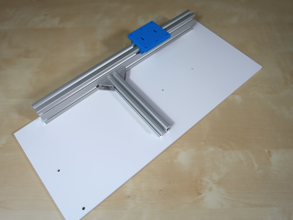
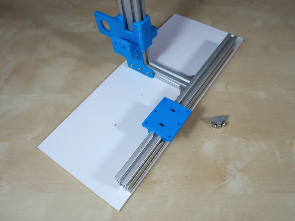
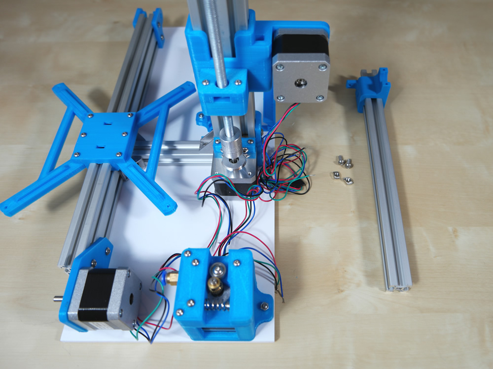
Take 4x M4 10mm Screws, 4x M4 Hammer Nut and the plate.
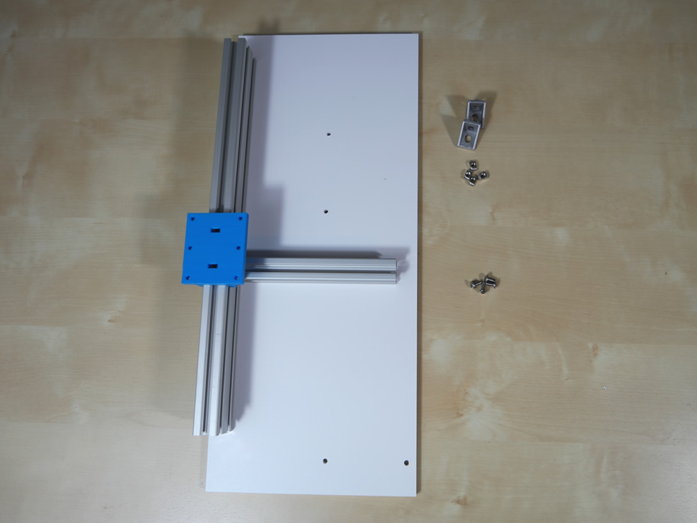
Now fixate the Alu Profiles on the plate.
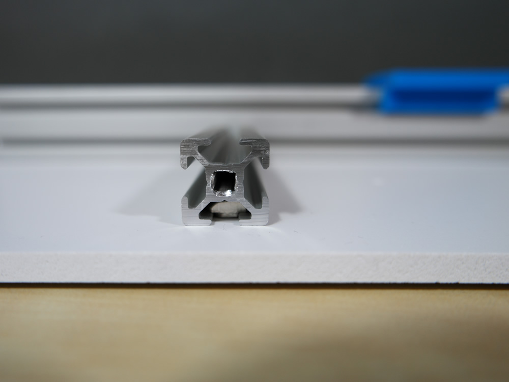
Your Hammer Nut must rotate 90 degrees.
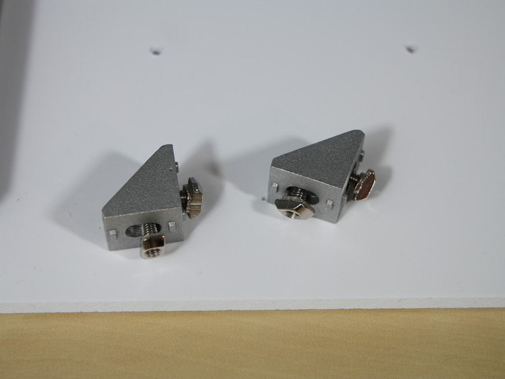
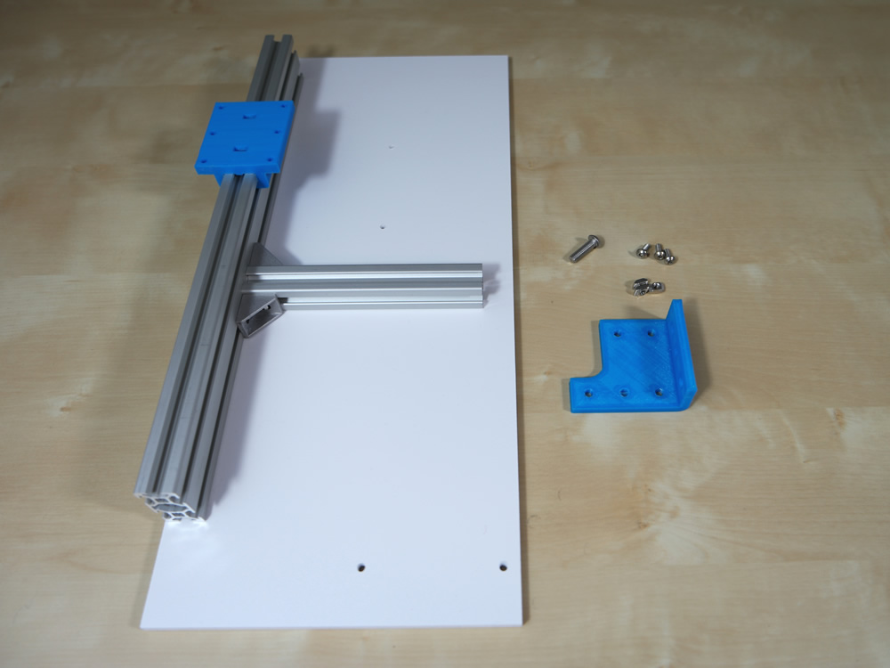
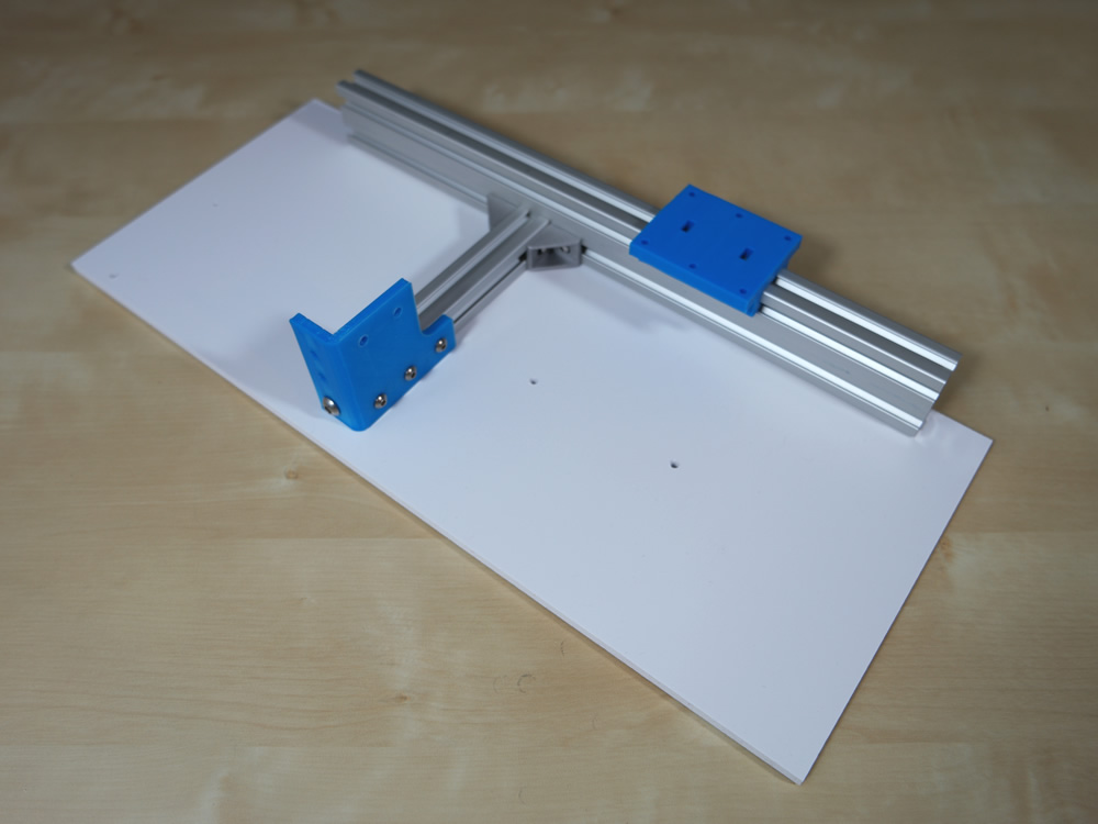
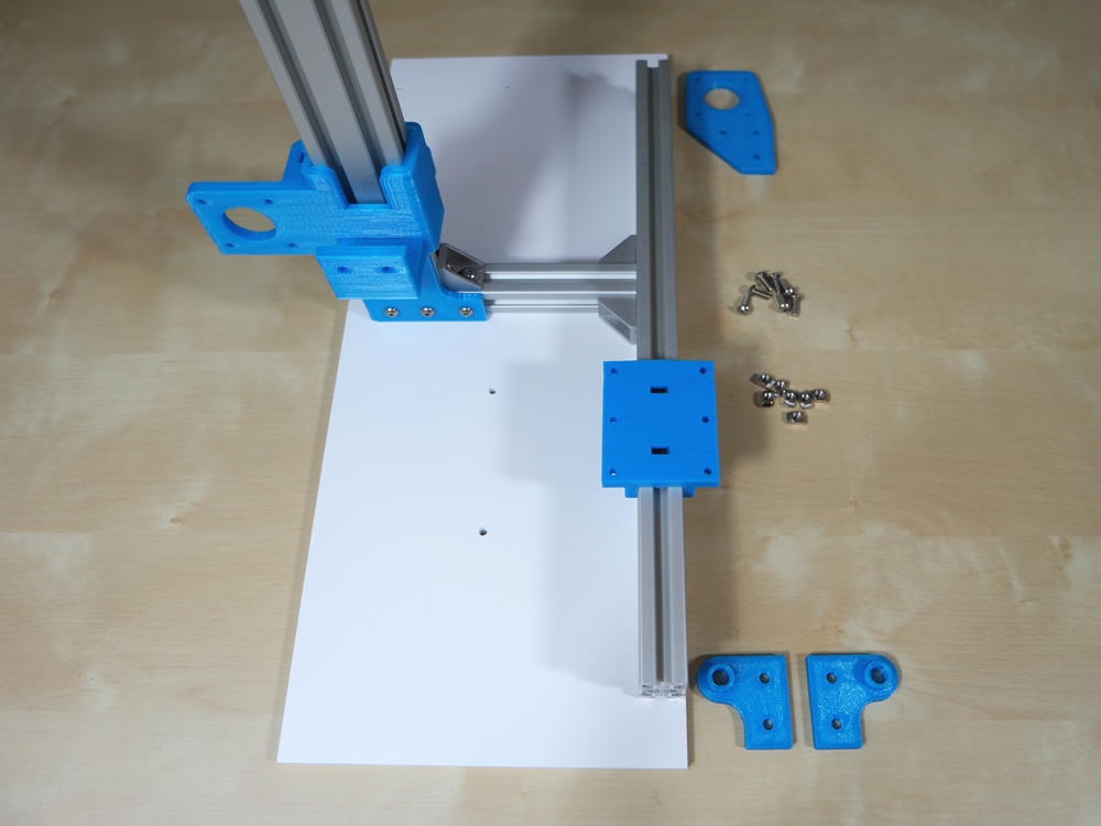
Use 4x M4 8mm Screws, 4x M4 Hammer Nut and 2x Fitting Angle.
Connect the Alu Profiles with the Fitting Angles.
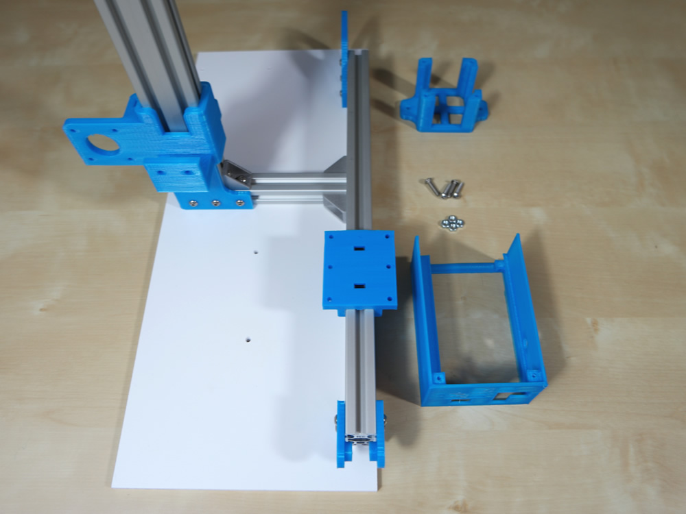
Step 2
- 1x Plastic Part
- 3x M4 Hammer Nut
- 3x M4 10mm Screw
- 1x M6 20mm Screw
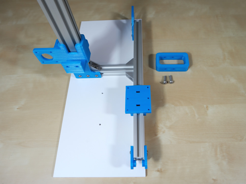
Connect the 3x M4 10mm screws on the plastic part.
After that, slide it into the Alu Profile and thighten the screws.
Step 3
- 1x Alu Profile 35cm
- 1x Fitting Angle
- 6x M4 Hammer Nut
- 2x M4 8mm Screw
- 4x M4 10mm Screw
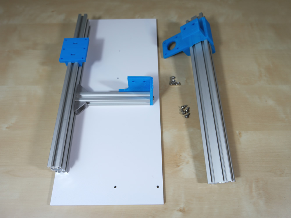
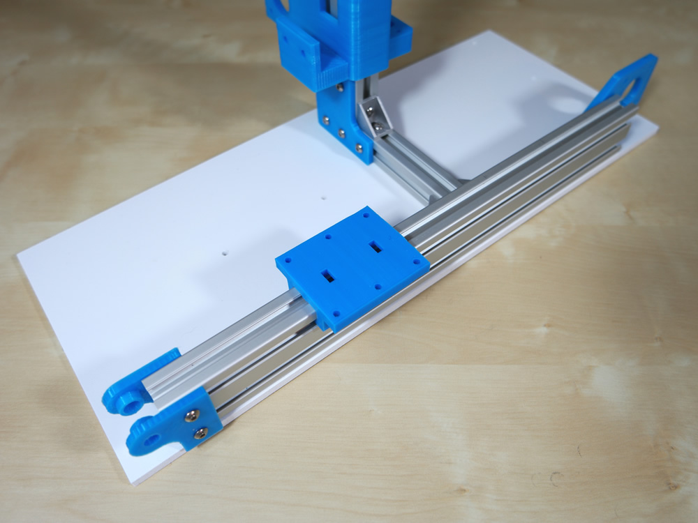
The same, first connect the screws on the plastic part.
After that, slide the Alu Profile from top and thighten the screws. Now fixate the Fitting Angle.
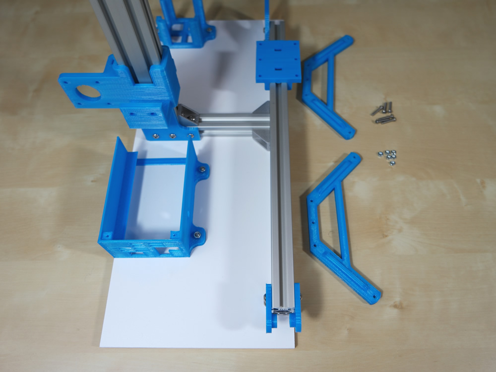
Step 4
- 3x Plastic Part
- 7x M4 Hammer Nut
- 7x M4 10mm Screw
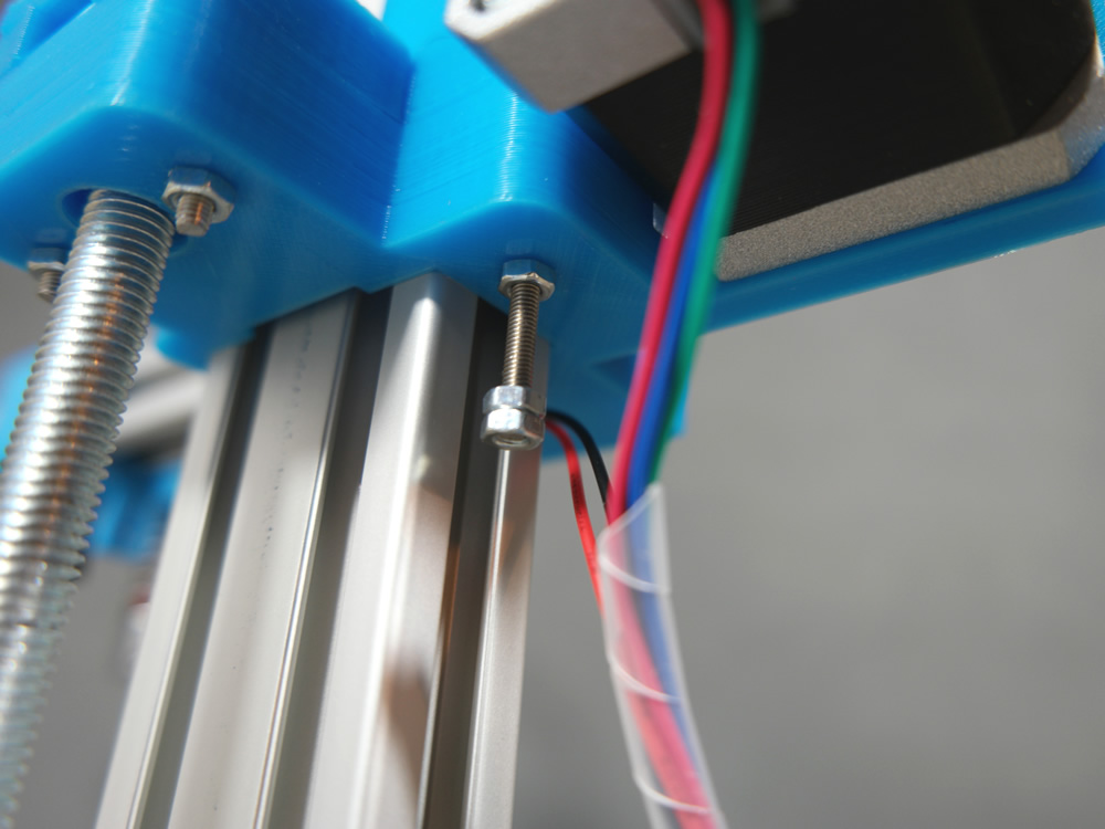
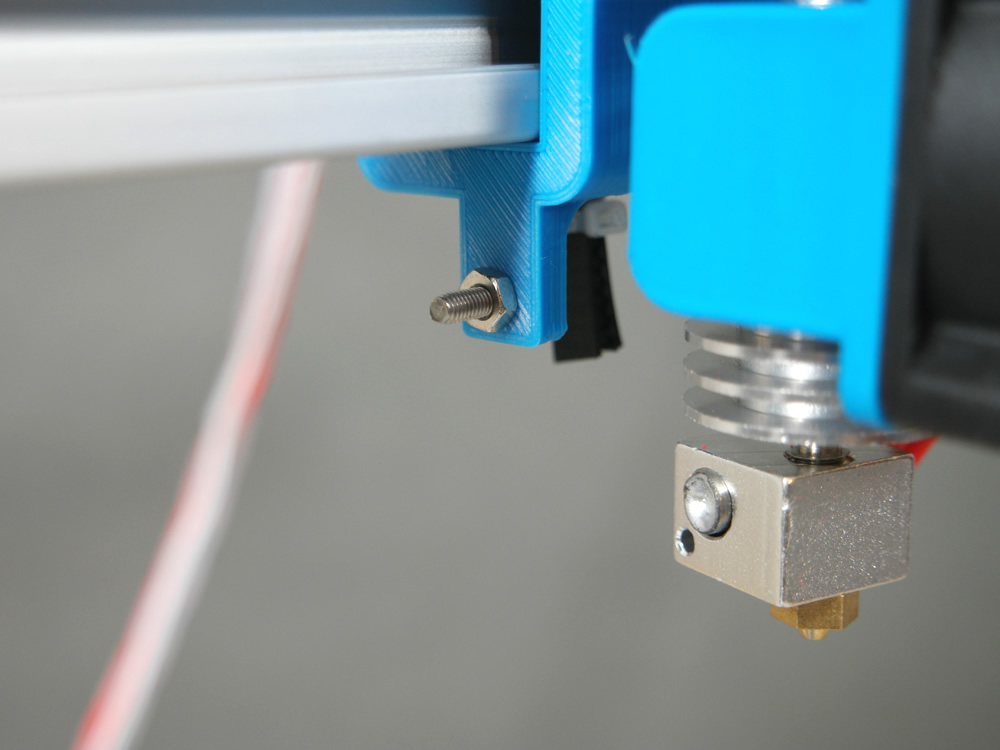
Loosely screw the nut onto the front plastic parts.
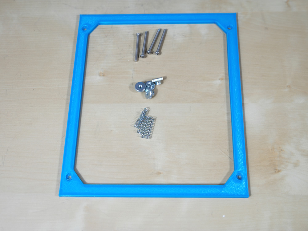
Step 5
- 1x Plastic Part
- 2x M6 20mm Screw
Fixate the handle on the Z axis Alu Profile.
Step 6
- 2x Plastic Part
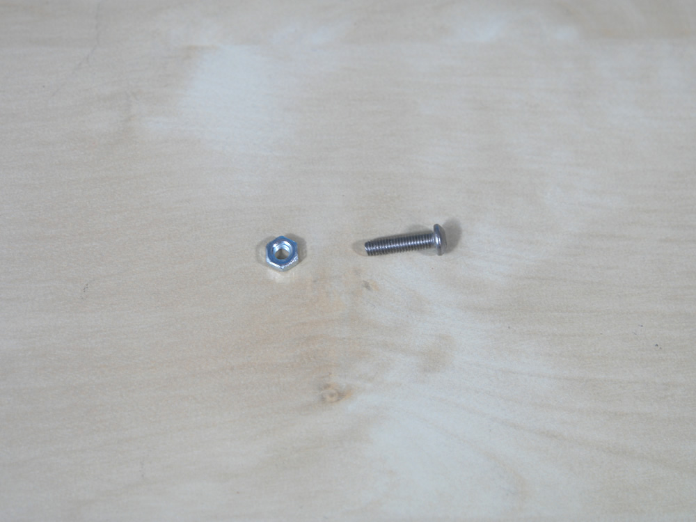
- 4x M4 Nut
- 4x M4 16mm Screw
Connect the stepper holder at the back of the plate and the ramps case in front.
Step 7
- 2x Plastic Part
- 6x M3 Nut
- 6x M3 16mm Screw
Step 8
- 2x Plastic Part
- 1x Pneumatic Connector
- 1x Extruder Gear
- 1x Extruder Bearing
- 1x Extruder Spring
- 1x Nema 17 Stepper
- 1x M3 8mm Screw
- 3x M3 12mm Screw
- 1x M3 20mm Screw
- 2x M3 25mm Screw
- 2x M3 30mm Screw
- 1x M4 8mm Screw
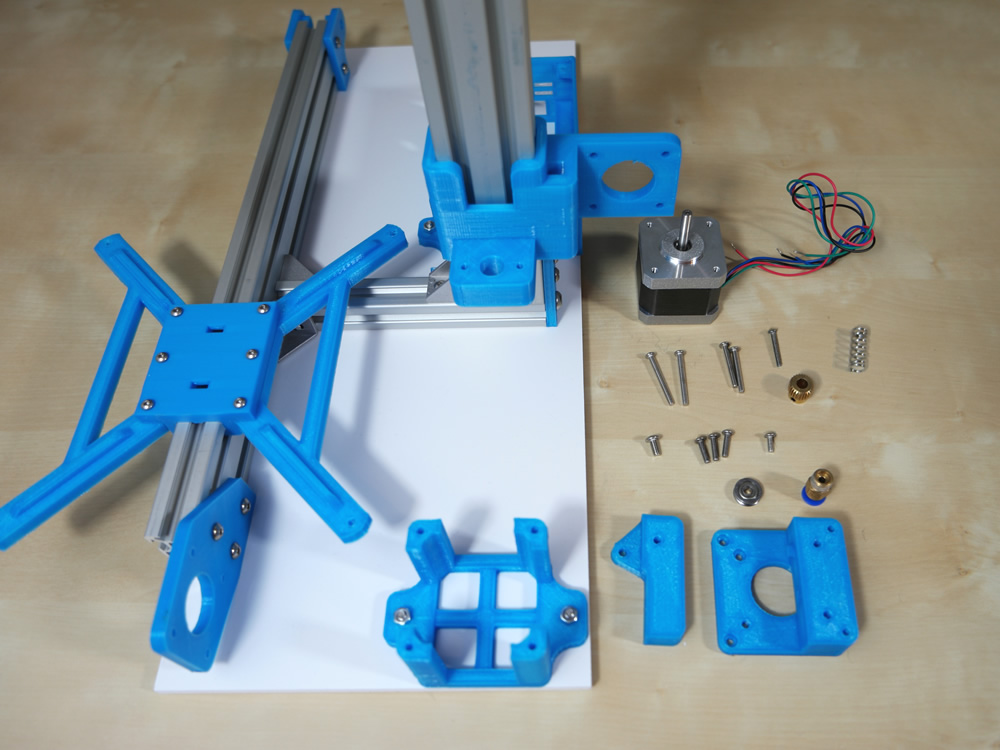
Put the nema 17 stepper into the holder. Now fixate the pneumatic connector with the plastic part.
After that, use 2x M3 30mm screws for the sockel (left side) and 2x M3 12mm screws for the right side.
Dont forget the extruder gear and fixate it.
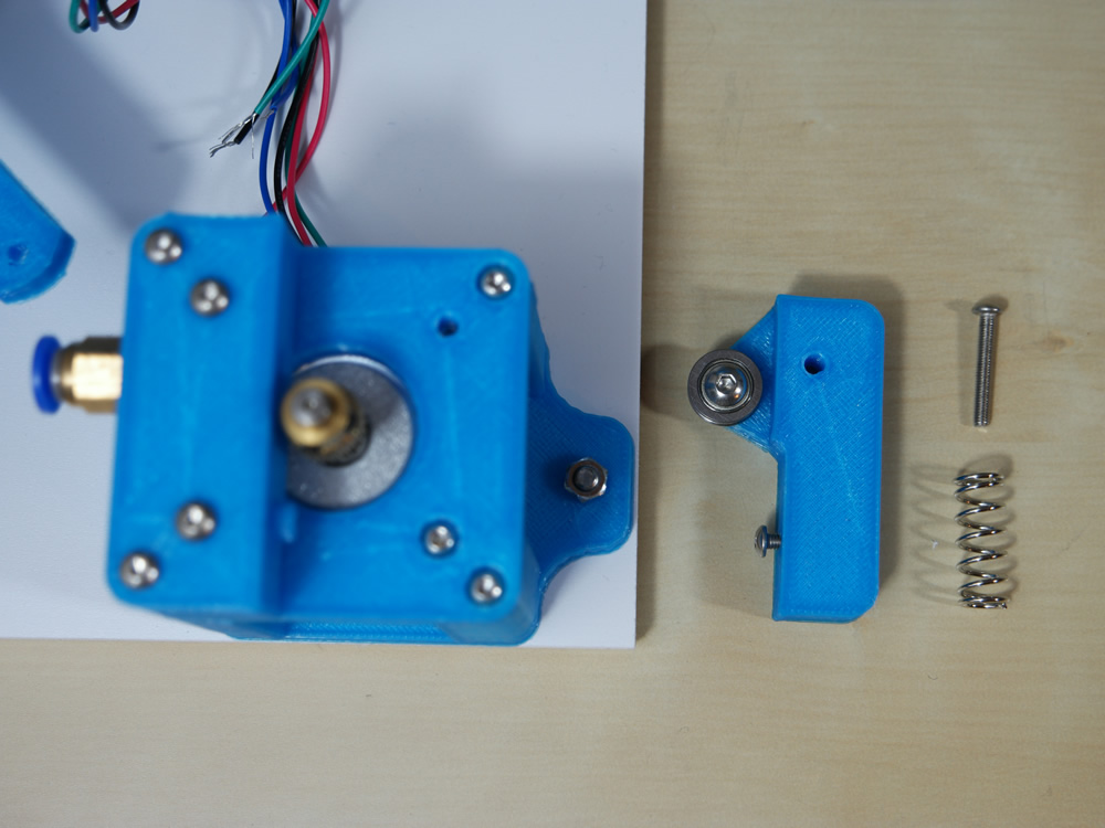
Now use the M4 8mm screw to connect the extruder bearing. The M3 12mm screw must into the plastic part.
Fixate the plastic part with a M3 20mm screw and use the spring between the plastic parts.
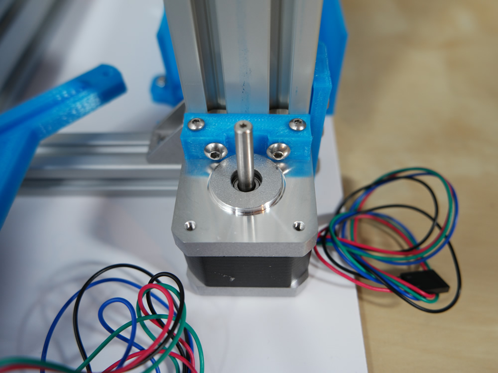
Step 9
- 1x Plastic Part
- 1x Nema 17 Stepper (with connectors)
- 2x M3 12mm Screw
- 2x M4 16mm Screw
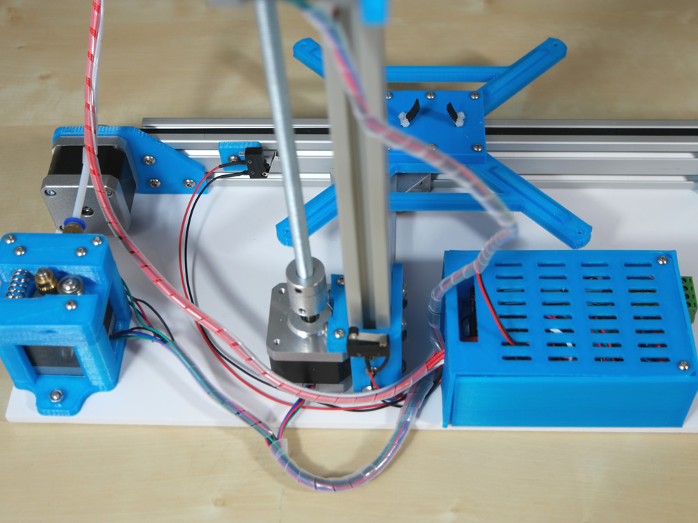
You must fixate the Nema 17 stepper on the Z Axis Alu Profile.
Step 10
- 1x Plastic Part
- 1x Flexible Coupling
- 2x M3 30mm Screw
- 2x M3 Nut
- 1x M8 Rod
- 1x M8 Nut
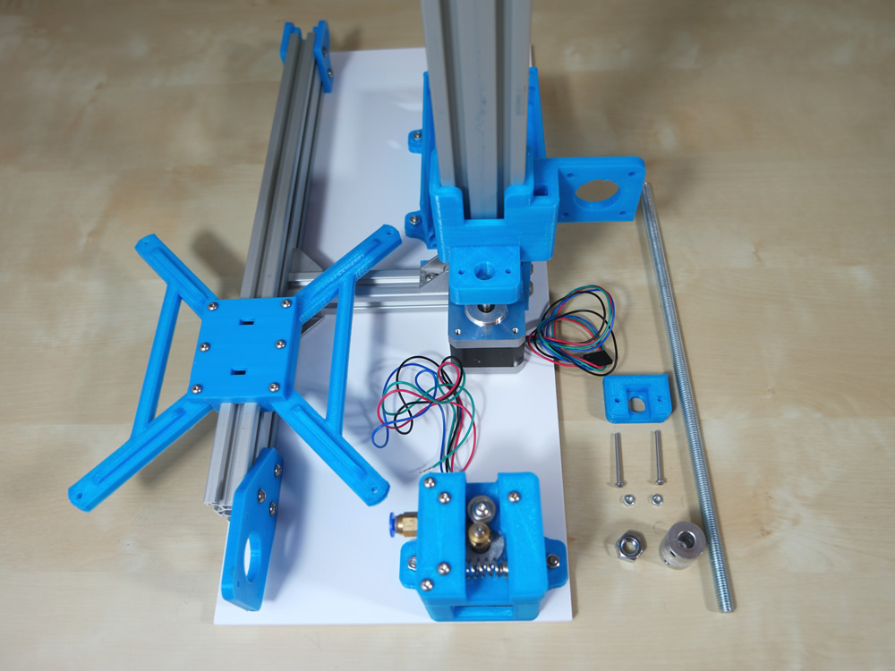
Put the M8 Nut into the plastic part and fixate it on the z axis plastic part with the M3 30mm screws.
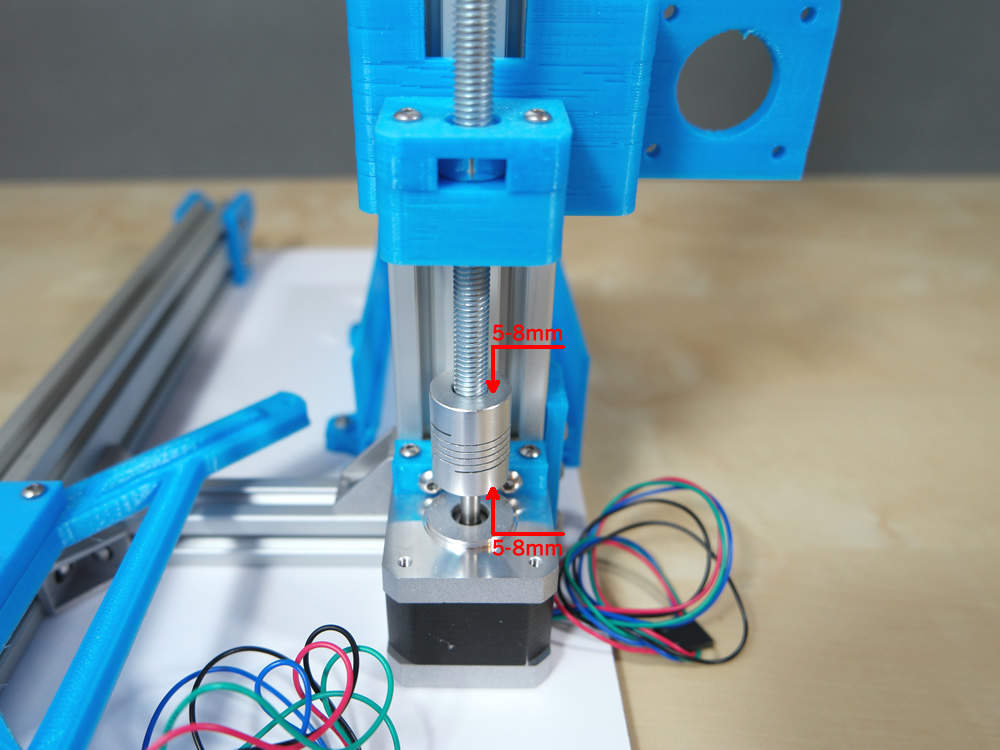
Please push the rod is not completely pure.
Step 11
- 2x Nema 17 Stepper
- 8x M3 8mm Screw
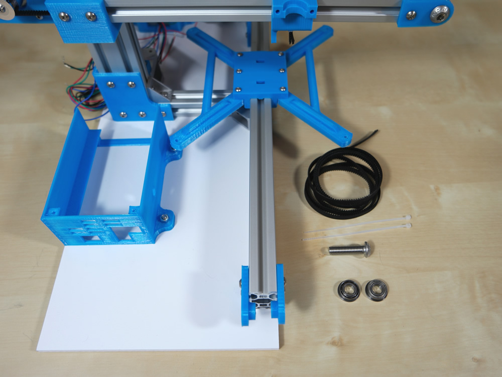
Step 12
- 1x Alu Profile 27cm
- 2x M4 10mm Screw
- 2x M4 Hammer Nut
You must fixate the Alu Profile 27cm (X Axis) on the XZ plastic part.
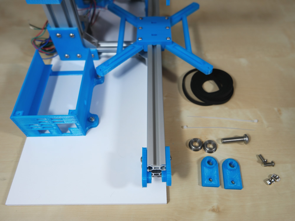
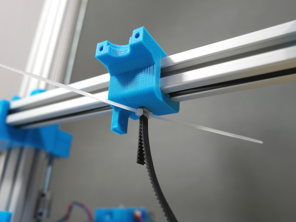
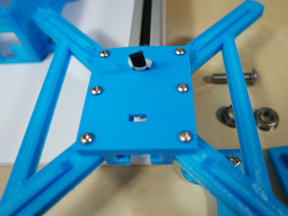
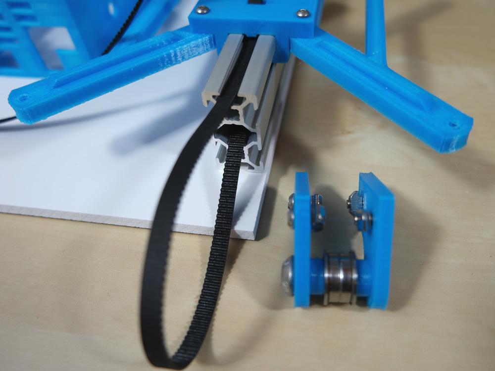
Step 13
- 2x Plastic Part
- 1x GT2 Belt
- 2x Cable Ties
- 2x Flanged bearing
- 2x M4 10mm Screw
- 2x M4 Hammer Nut
- 1x M8 30mm Screw

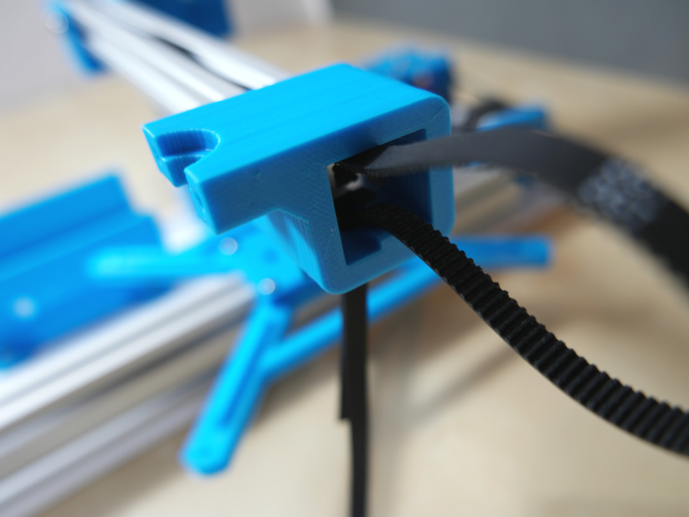
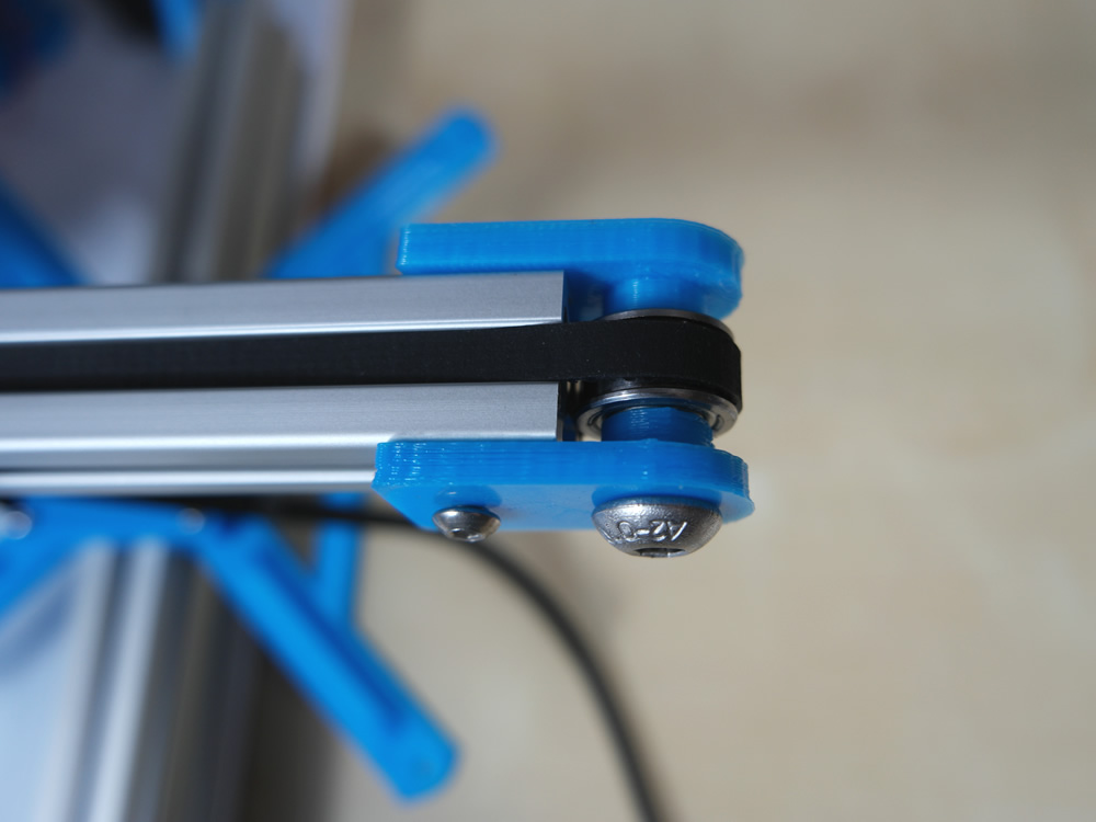

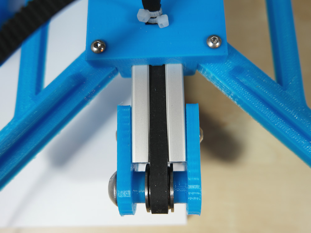
Step 14
- 1x GT2 Belt
- 2x Cable Ties
- 2x Flanged bearing
- 1x M8 30mm Screw
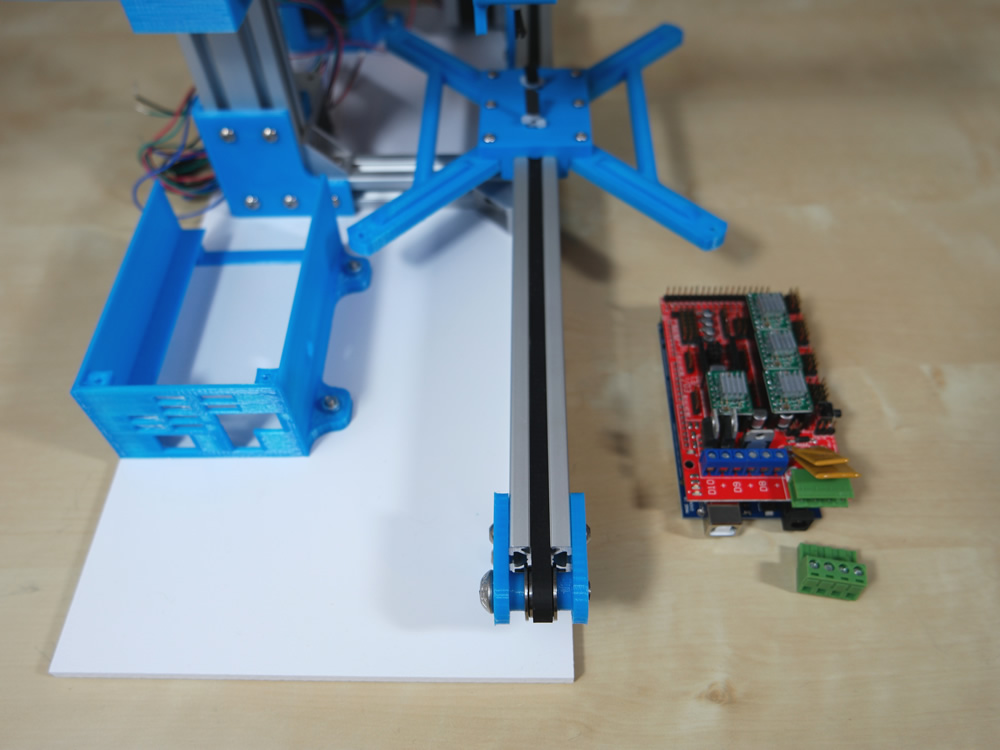
Step 15
- 1x Ramps 1.4 Board + Arduino
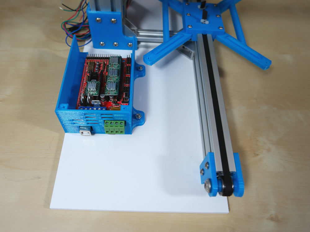
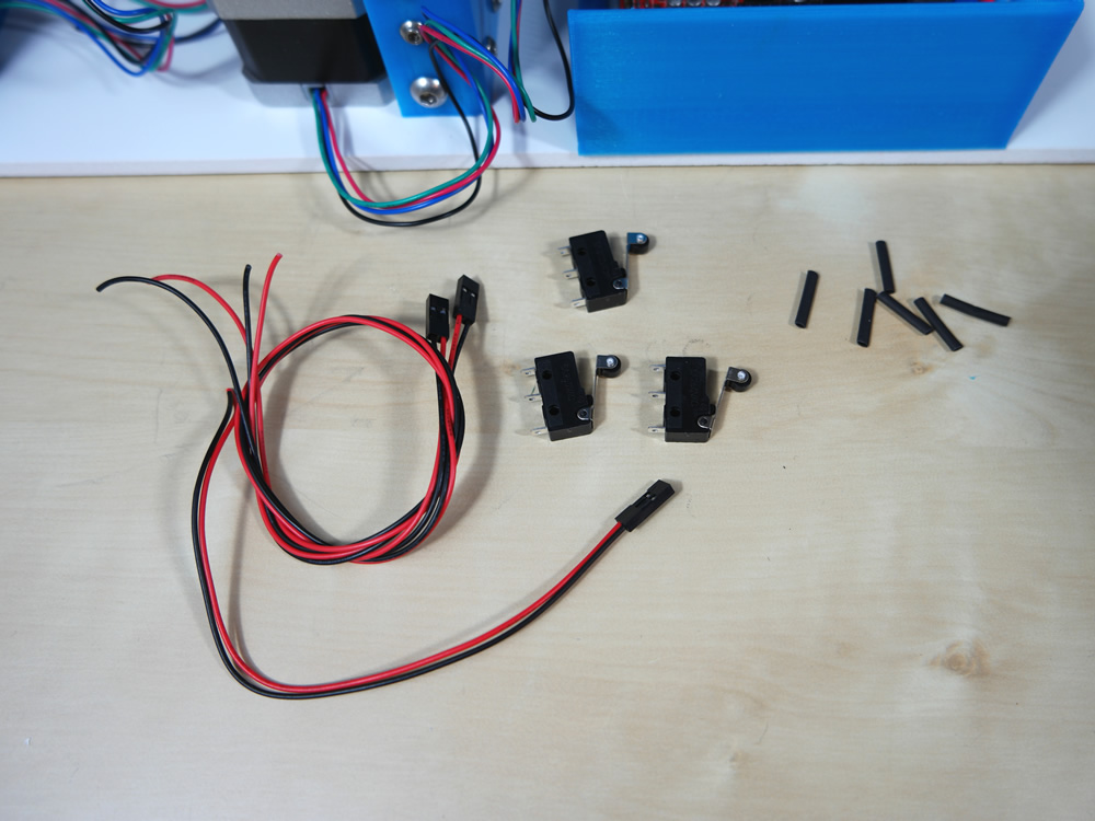
Step 16
- 3x Endstop
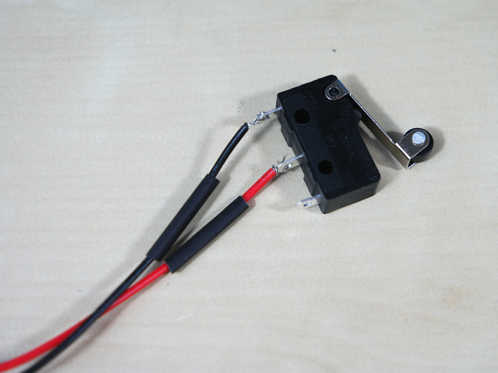
- 3x Cable 2 Pin
- 6x Heat Shrink Tube (15mm)

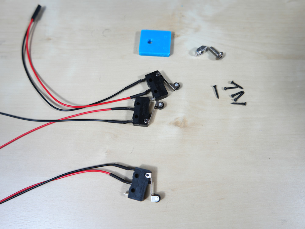
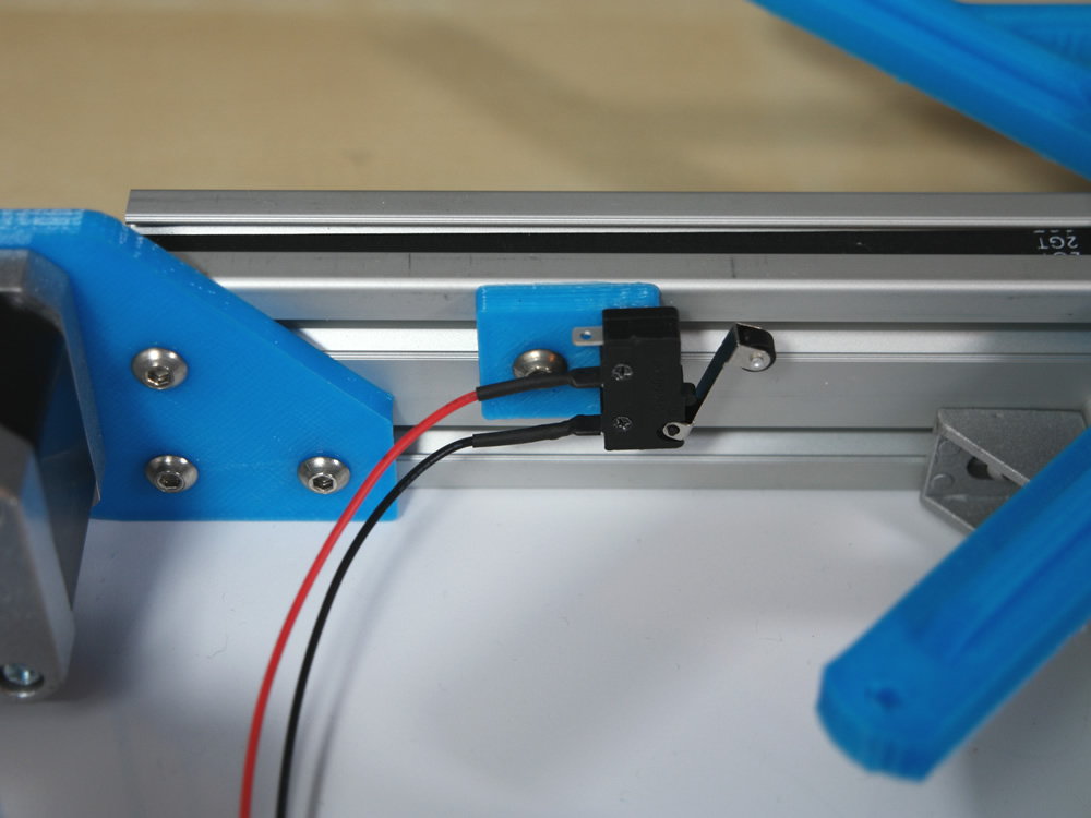
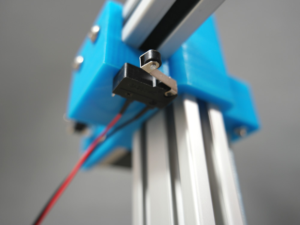
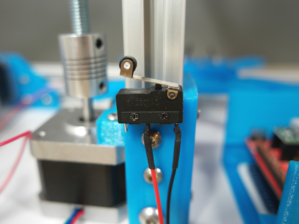
Step 17
- 1x Plastic Part
- 3x Endstop
- 6x M1.4 12mm Screw
- 1x M4 Hammer Nut
- 1x M4 10mm Screw
Step 18
- 3x Cable 3 Pin
- 3x Nema 17 Stepper cable sets
- 12x Heat Shrink Tube (15mm)
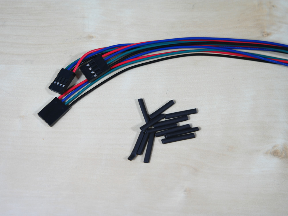
You only need 20-25cm long cables. Measure rough and cut of.
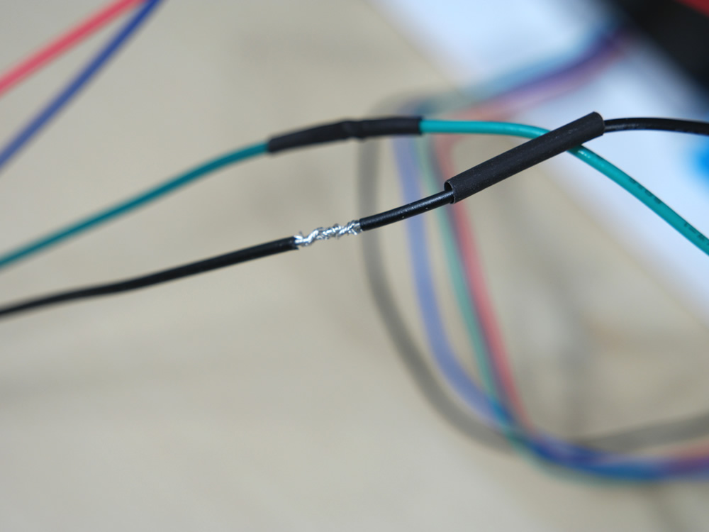
Turn the cable into each other or solder it.
Step 19
- 1x Cable red/black 1m
- 1x Fan
- 2x Heat Shrink Tube (15mm)
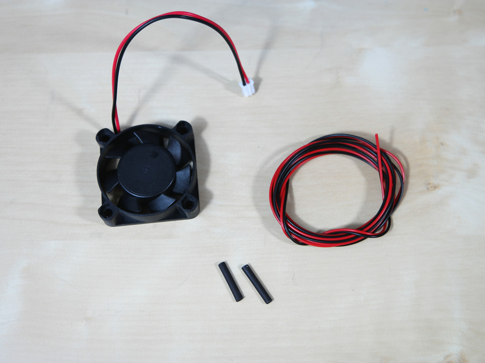
Cut the plug off
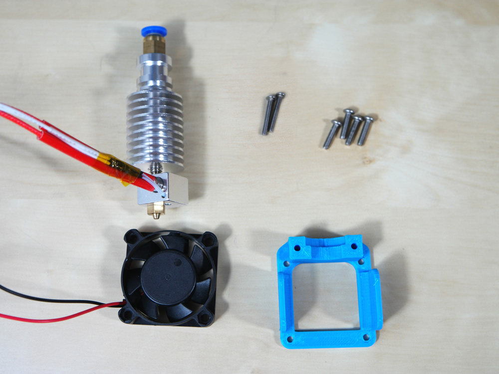
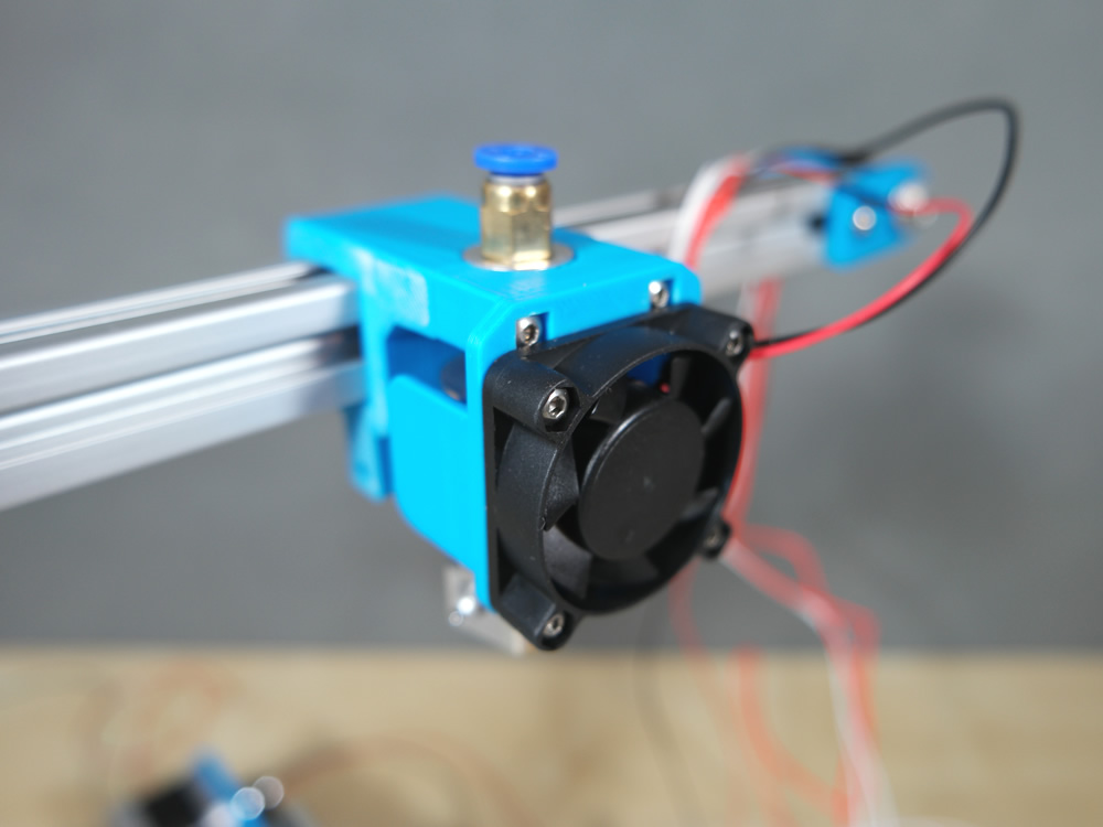
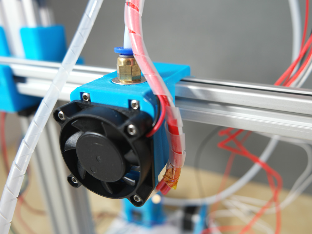
Step 20
- 1x Plastic Part
- 1x Hotend
- 1x Fan
- 2x M3 20mm Screw
- 4x M3 12mm Screw
Step 21
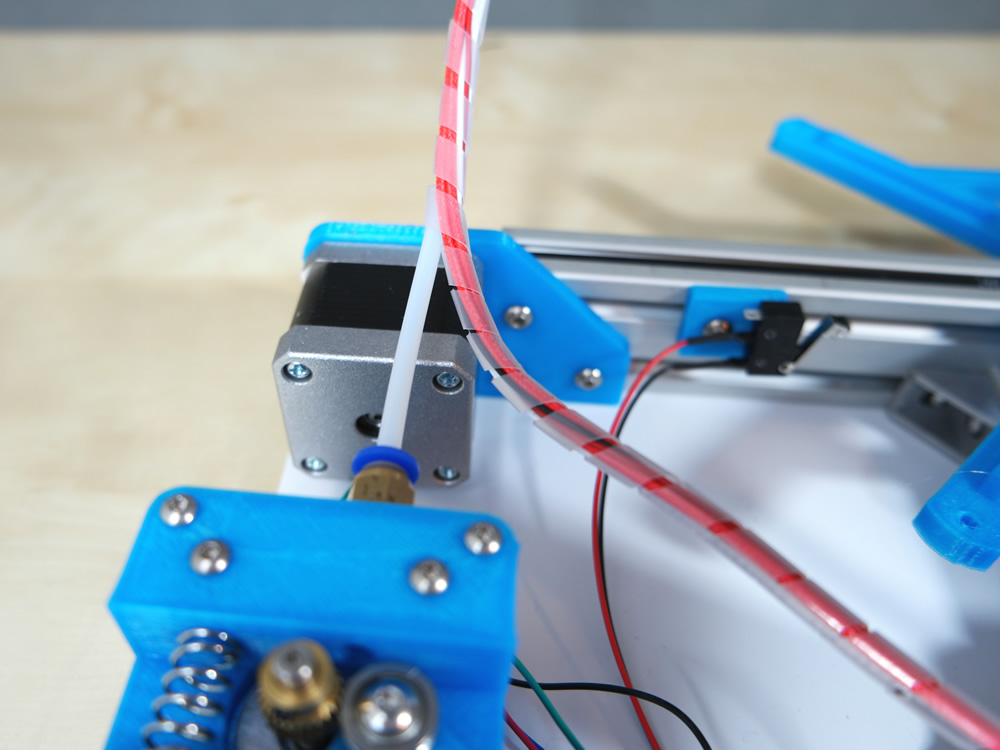
- 1x Bowden Tube
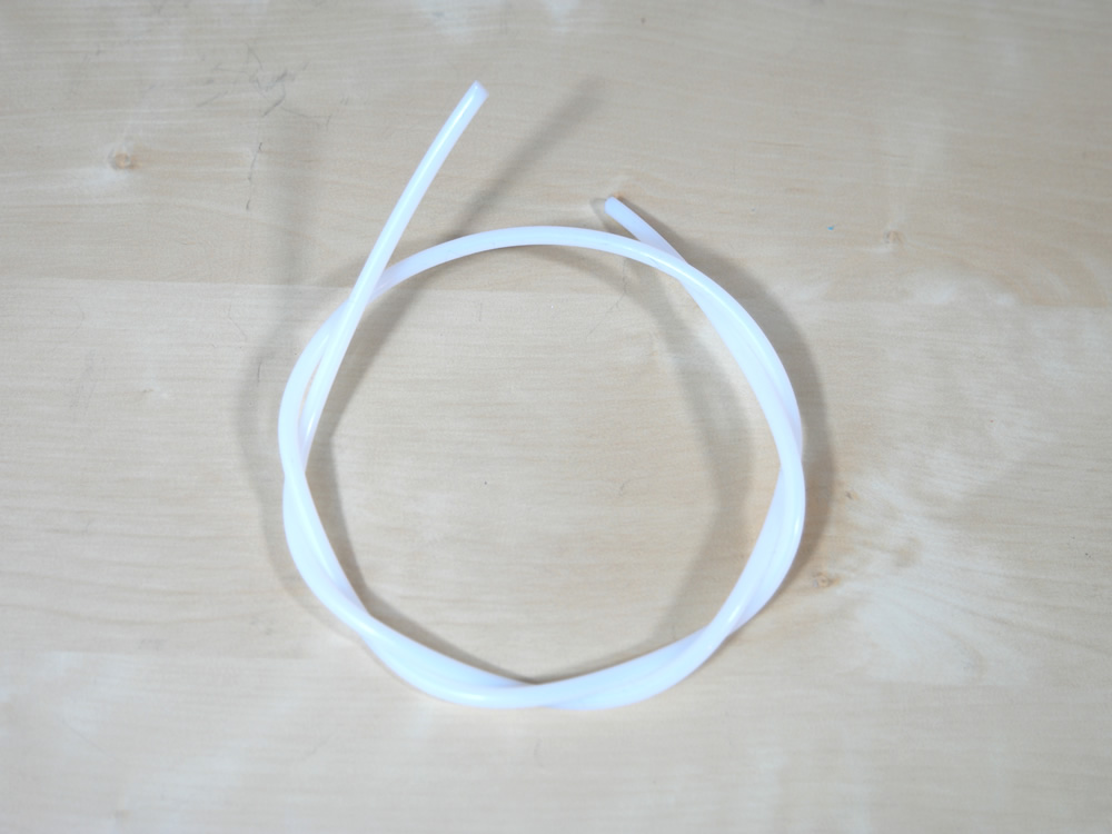
You only need a 60cm long bowden tube. Connect it into the pneumatic connectors.
Step 22
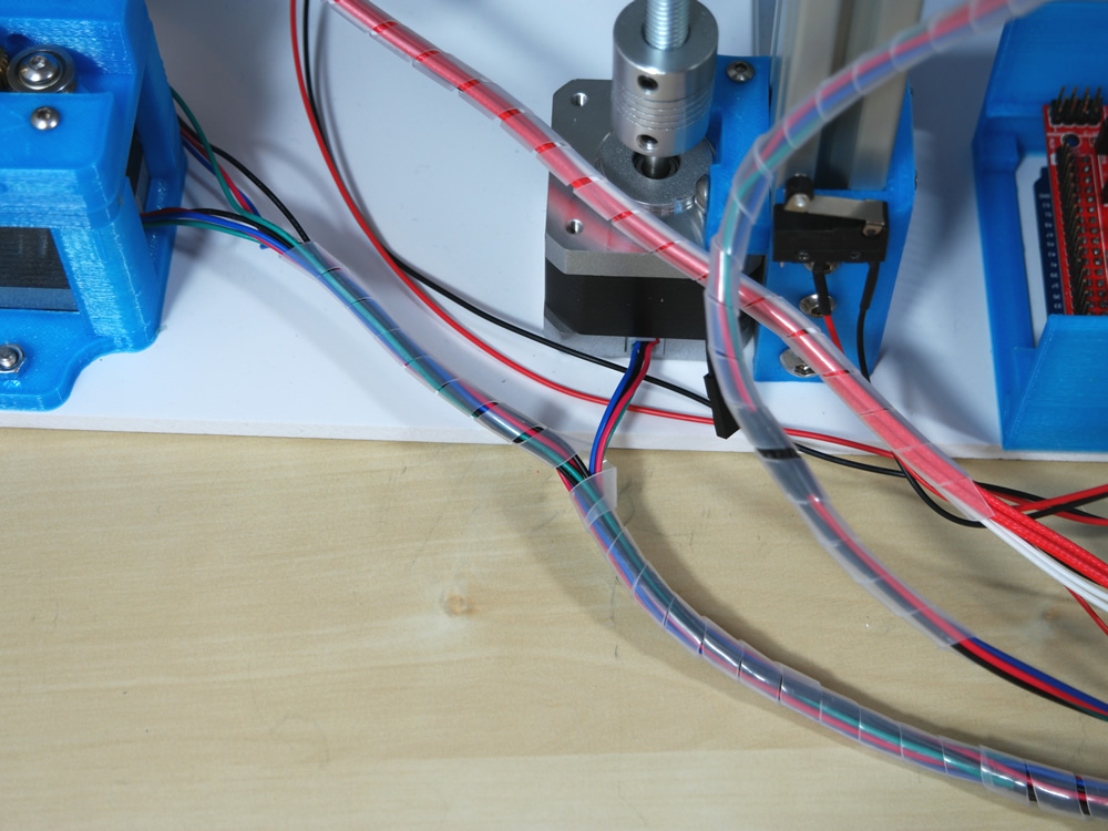
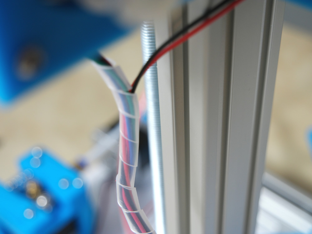
- 1x Spiral Band

Step 23

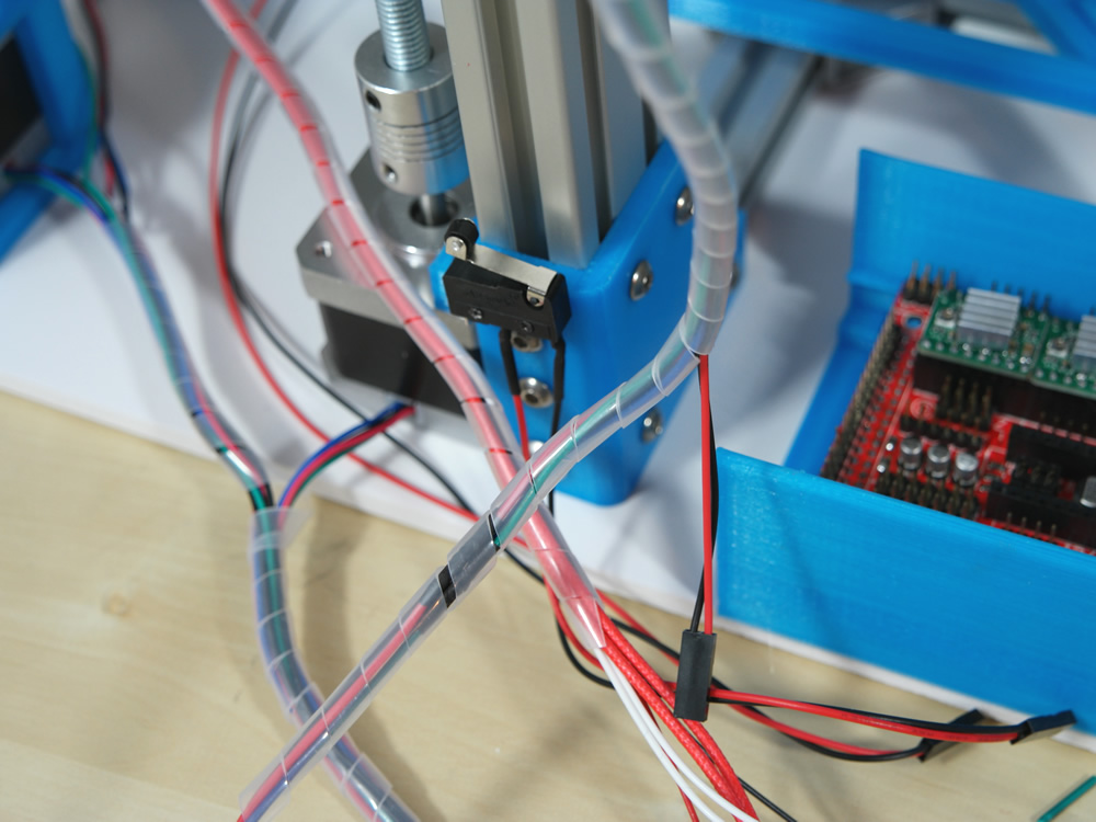
Now connect the pins and cables.
Step 24
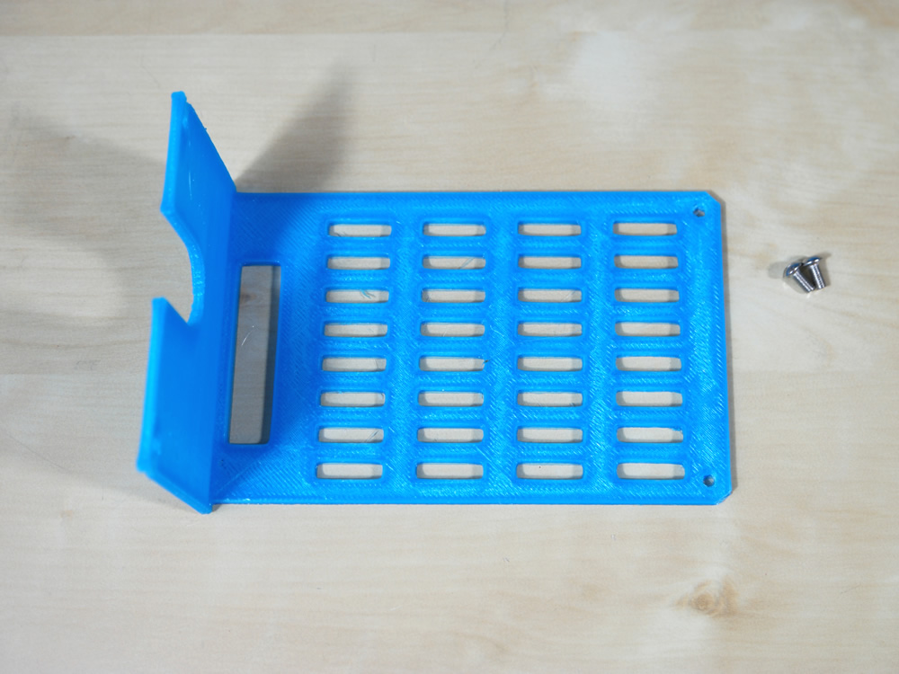
- 1x Plastic Part
- 3x M3 6mm Screw
Step 25
- 1x Spring
- 3x M3 Nut
- 1x M3 40mm Screw
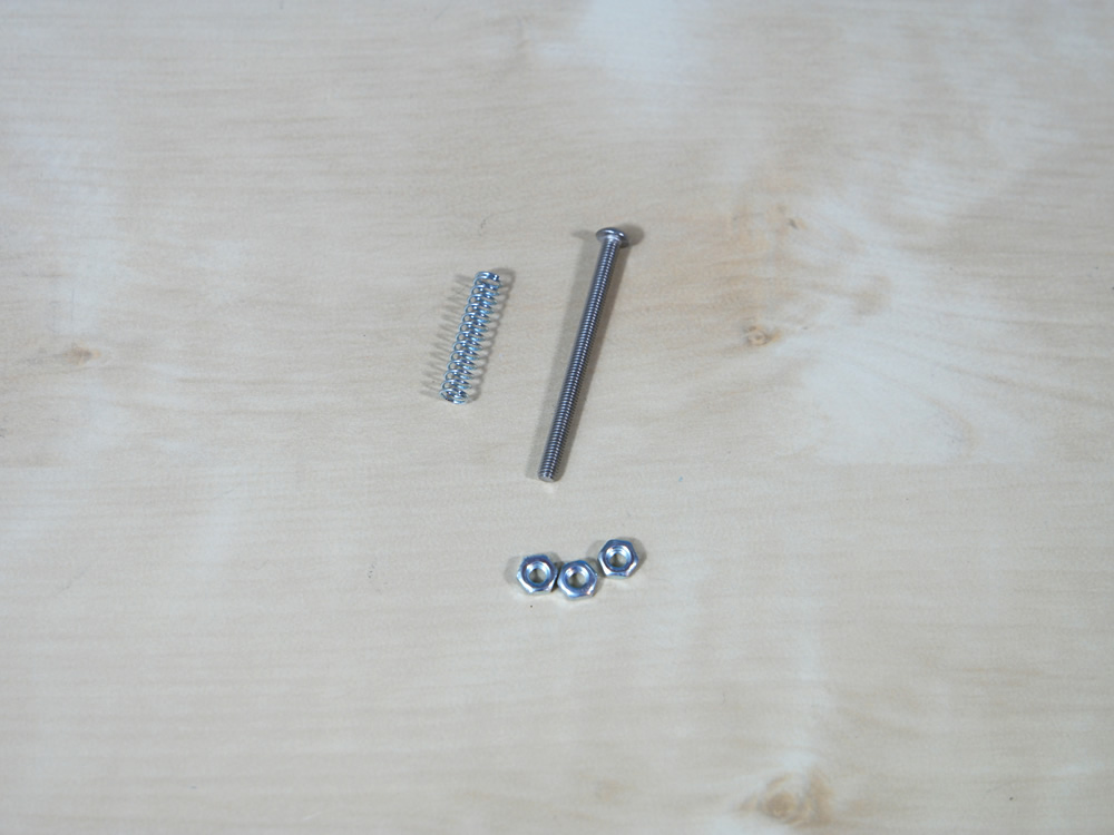
Push the screw all the way down and fixate it. Use two nuts for the endstop.

Step 26
- 1x M3 Nut
- 1x M3 12mm Screw
Step 27
- 4x Spring
- 4x Knurling Nut
- 1x M3 30mm Screw

Step 28
- 4x Spring
- 4x Knurling Nut
- 1x M3 30mm Screw

Step 29
- 1x Cable red/black 10cm
- 1x DC Connector
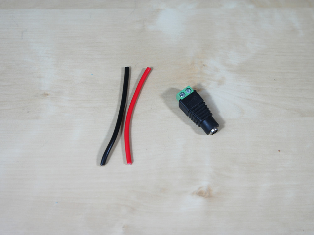
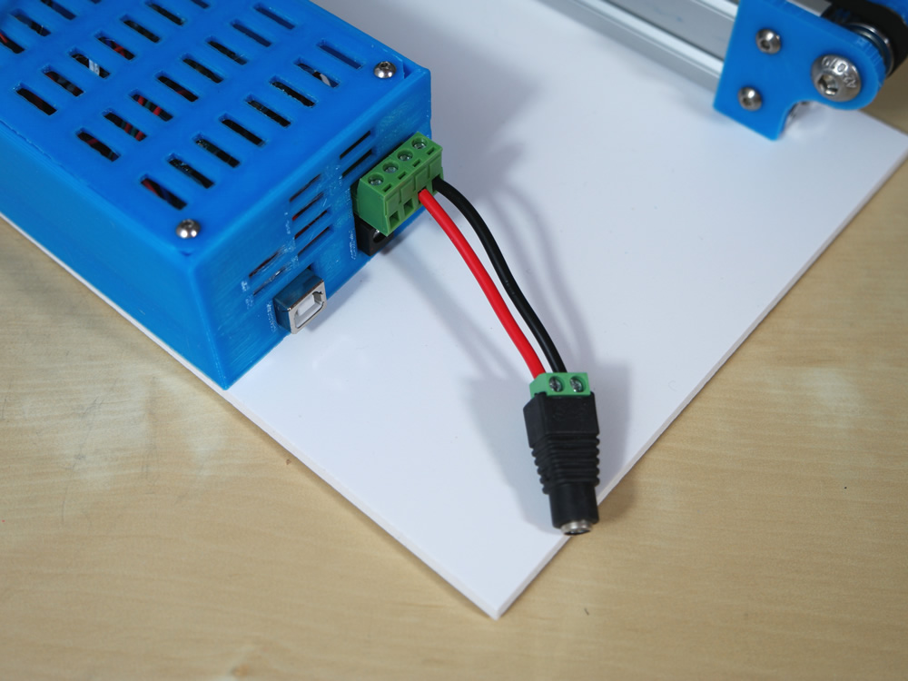
Attention!!! Red cable -> Ramps + to DC connector +, Black cableto Ramps - -> DC connector -
Step 30
Install Arduino IDE and open the Marlin.ino from our TekBOT firmware. Now connect your 3D Printer to your PC (no Power cable only USB). Check your Arduino Settings (Board Arduino Mega, USB Port: XXX) and click on compile and upload.
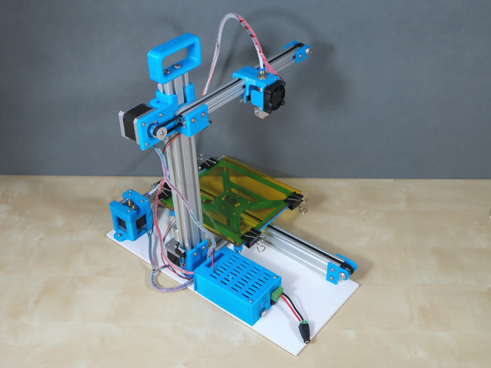
Finish :)